




Hardware — Specifications, BOM & Assembly
OpenArm hardware documentation: general and motor specifications, bill of materials with procurement guide, assembly instructions including CAD files, wiring harnesses, and casing components.
Also see the OpenArm hardware hub.
On this page
- General Specifications
- Motor Specifications
- Gripper Specifications
- Bill of Materials
- Actuators
- Mechanical Components
- Electrical Components
- How to Procure
- Assembly Guide
- CAD Files
- Motor ID Setup
- Wiring & Casing
OpenArm Docs
Also see
Complete hardware documentation: mechanical and motor specifications, bill of materials with procurement guide, CAD file access, motor ID configuration, and wiring details.
DAMIAO Motors SocketCAN Aluminum Frame Open Hardware
Source: docs.openarm.dev/hardware/ License: CERN-OHL-S-2.0 Last updated: Apr 6, 2026
1. General Specifications
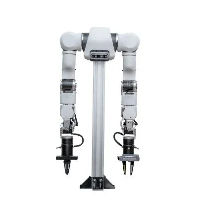
OpenArm features a small human-like physique with support pillars made of MiSUMi aluminum frames for easy dimension adjustment and attachment of cameras and sensors. The base plate features evenly spaced M6 taps for mounting to surfaces.
| Property | Value |
|---|---|
| Degrees of Freedom | 7 DOF per arm |
| Design Scale | Human-scale, proportioned for ~160–165 cm person |
| Nominal Payload | 4.1 kg (weight held for 1 min in worst posture with arms extended) |
| Peak Payload | 6.0 kg (moved to worst posture over 3 sec, held for 1 sec) |
| Frame Material | Aluminum (structural), stainless steel (critical joints) |
| Base Mounting | Evenly spaced M6 tapped holes |
| Support Pillars | MiSUMi aluminum frames (adjustable) |
| Communication | SocketCAN (Linux CAN-bus) |
| Motor Type | QDD (Quasi-Direct Drive) backdrivable |
| CAD Files | STEP, STL, Fusion 360 (open source) |
| Hardware License | CERN Open Hardware Licence Version 2 — Strongly Reciprocal |
Payload Note The payload value includes the end-effector weight. For example, a 1.5 kg end-effector reduces nominal payload to 2.6 kg and peak payload to 4.5 kg.
Each joint includes mechanical limits restricting motion range for safety purposes. These limits also protect internal wiring from over-rotation damage.
2. Motor Specifications
OpenArm incorporates the DAMIAO 43 series and DAMIAO 8009P motors, with different models selected for each joint to balance high payload capacity with a clean, compact appearance. Motors with cross-roller bearings are used in single-support sections for enhanced rigidity and precision.
Motor Assignment by Joint
| Joint | Motor Model |
|---|---|
| J1, J2 (shoulder) | DM-J8009P-2EC |
| J3 | DM-J4340P-2EC |
| J4 | DM-J4340-2EC |
| J5, J6, J7, J8 (wrist/gripper) | DM-J4310-2EC V1.1 |
Detailed Motor Specifications
| Parameter | DM-J4310-2EC V1.1 | DM4340 series | DM-J8009P-2EC |
|---|---|---|---|
| Rated Voltage | 24 V | 24 V | 24 V (supports 24–48 V) |
| Rated Current | 2.5 A | 2.5 A | 20 A |
| Peak Current | 7.5 A | 8 A | 50 A |
| Rated Torque | 3 Nm | 9 Nm | 20 Nm |
| Peak Torque | 7 Nm | 27 Nm | 40 Nm |
| Rated Speed | 120 rpm | 36 rpm | 24 V: 100 rpm / 48 V: 200 rpm |
| Max No-Load Speed | 200 rpm | 52 rpm | 24 V: 160 rpm / 48 V: 320 rpm |
| Reduction Ratio | 10:1 | 40:1 | 9:1 |
| Pole Pairs | 14 | 14 | 21 |
| Phase Inductance | 340 μH | 317 μH | 61 μH (at 25 °C) |
| Phase Resistance | 650 mΩ | 760 mΩ | 90 mΩ (at 25 °C) |
| Outer Diameter | 56 mm | 57 mm | 98 mm |
| Height | 46 mm | 53.3 mm | 61.7 mm |
| Weight | 300 g | 362 g | 896 g |
| Encoder Bits | 14-bit | 14-bit | 14-bit |
| Number of Encoders | 2 | 2 | 2 |
| Encoder Type | Magnetic (single-turn) | Magnetic (single-turn) | Magnetic (single-turn) |
| Control Interface | CAN | CAN | CAN |
Note The actual motor used for J1/J2 is the DM8009P. Specifications are nearly identical to the DM8009 datasheet. All motors use CAN communication protocol.
3. Gripper Specifications
| Property | Value |
|---|---|
| Maximum Jaw Separation | 88 mm |
| Fully Closed State | Jaws contact each other |
| Rotor Travel (closed → open) | 60° |
| Zero Point | Motor zero aligns with fully closed state |
| Mechanism | Ball-bearing slider blocks, rails, and linkage bearings |
Custom End-Effector Integration
OpenArm supports custom end-effectors by replacing the J8_B interface part. When designing a custom attachment:
- Match original hole patterns and dimensions of
J8_B - Include mounting features compatible with your end-effector
- Maintain structural integrity and alignment
- Consider balanced mass distribution relative to the arm's axis
- Plan cable routing to avoid snags during full range of motion
- Design for 3D printing or CNC machining manufacturability
CAD files for the J8_B interface are available in the openarm_hardware repository.
4. Bill of Materials
All prices listed below are in Japanese Yen (¥), as the primary sourcing platform is MISUMI Japan. International buyers should check for regional MISUMI sites or alternative distributors.
Actuators (Total: ¥397,356)
| Component | Qty | Model | Cost |
|---|---|---|---|
| J1, J2 motors (per arm) | 4 (bimanual) | DM-J8009P-2EC | ¥205,790 |
| J3 motor (per arm) | 2 (bimanual) | DM-J4340P-2EC | ¥42,066 |
| J4 motor (per arm) | 2 (bimanual) | DM-J4340-2EC | ¥37,387 |
| J5, J6, J7, J8 motors (per arm) | 8 (bimanual) | DM-J4310-2EC V1.1 | ¥112,113 |
Mechanical Components (Total: ¥478,518)
| Component | Cost |
|---|---|
| Manufactured Arm Parts (MEVIY) | ¥316,018 |
| Off-the-shelf Arm Parts | ¥34,336 |
| Pedestal Components | ¥20,222 |
| Gripper Components | ¥107,942 |
Electrical Components (Total: ¥84,564)
Electrical components include: 24 V / 15 A power supply, USB to CANFD converter, and emergency stop switch. PCBs and wiring harnesses are custom-designed with fabrication files provided in the repository.
Procuring Components
Off-the-Shelf Parts (MISUMI)
Most mechanical and fastener components are available as catalog items from MISUMI.
Visit the MISUMI website. Go to misumi.com and select your region.
Search by model number. Enter the part number (e.g.,
CBE4-8) in the search bar.Confirm dimensions/specs. Verify the part matches the BOM specifications.
Add to cart and order. No drawings needed for catalog parts — model numbers are sufficient.
Manufactured Parts (MEVIY)
Some components require custom manufacturing via MEVIY, MISUMI's automated 3D machining service. Two ordering methods:
Method 1: Upload CAD File
Go to MEVIY. Visit the MEVIY website and create an account.
Upload STEP file. Download the STEP file from openarm_hardware and upload it.
Select material, finish, tolerances. Review the automated quote.
Place order. Confirm specifications and submit.
Method 2: Use Pre-registered Model Numbers (Recommended)
Visit MISUMI's search page.
Paste the BOM model number. Example:
MVBLK-ASN-48S-4BGUX-L. MEVIY automatically identifies it as a custom part.Specify quantity and order. No CAD upload required — the geometry is pre-validated.
Tip Method 2 ensures you get the exact geometry that has been validated for OpenArm. Use Method 1 only if you need to review or customize the design.
Custom PCBs (JLCPCB)
Download files. Get the Gerber + BOM + CPL files from the project repository.
Upload to JLCPCB. Go to jlcpcb.com and upload the Gerber zip file to get a quote.
Configure options. Leave default settings unless you have specific requirements. Optionally choose
Remove Markin theMark on PCBoption.Enable PCB Assembly. Scroll to the PCB Assembly tab and enable it, then click Next.
Upload BOM and CPL files. Click Process BOM & CPL and review the parts list.
Review 2D/3D models and proceed to place the order.
Custom Wires and Harnesses (LCSC)
Go to LCSC custom cable page.
Upload wiring drawings. Use drawings provided in the openarm_hardware repository.
Input desired quantity and click Confirm your cable plan.
Submit cable order. LCSC will send a quote for final ordering.
5. Assembly Guide
Step 0: Find CAD Files
The project makes all 3D models publicly available through GitHub to promote openness and customization.
What's included in the repository:
- STEP Files — For manufacturing and modification in any CAD tool
- STL Files — Ready for 3D printing of all printed components
- Attachments — Camera mounts, PCB hubs, and custom pieces
- Wiring Diagrams — For cable manufacturing reference
Hardware License CAD files are released under the CERN Open Hardware Licence Version 2 — Strongly Reciprocal. You are free to use, modify, and manufacture, but must share modifications under the same license.
Repository: github.com/enactic/openarm_hardware
Motor ID Configuration
Before assembling, each DAMIAO motor must be assigned the correct CAN ID using the Damiao Debugging Tools software (Windows). Configuration is done over UART (serial), not CAN.
Motor ID Reference Table
| Joint | Sender CAN ID | Receiver (Master) ID |
|---|---|---|
| J1 | 0x01 | 0x11 |
| J2 | 0x02 | 0x12 |
| J3 | 0x03 | 0x13 |
| J4 | 0x04 | 0x14 |
| J5 | 0x05 | 0x15 |
| J6 | 0x06 | 0x16 |
| J7 | 0x07 | 0x17 |
| J8 (Gripper) | 0x08 | 0x18 |
Motor ID Configuration Steps
Download Damiao Debugging Tools. The Windows executable is available from Damiao. Allow through Windows Defender if blocked.
Connect via UART serial at 921600 bps. Use a USB-serial adapter — not a CAN adapter for this step.
Click "ReadParam" to retrieve current motor parameters and verify connection.
Select correct Sender and Master IDs from the reference table above.
Input values into the corresponding fields in the software.
Click "WriteParam" to save settings permanently to the motor.
Power Supply Requirements for Motor Configuration
| Motor | Required Current |
|---|---|
| DM-J4310 / DM-J4340 | 0.3 A |
| DM-J8009P | 0.75 A |
Troubleshooting — Motor starts but doesn't rotate Verify adequate power supply using the current reference above. On CANable devices, enable the 120 Ω termination resistor. Daisy-chained motors require the summed current of all connected units.
6. Wiring & Casing
Cable Types
Five cable types are needed for the full bimanual assembly:
| Cable Type | Quantity |
|---|---|
| J1 & J2 cables | 4 |
| J3–J4 cables | 2 |
| J4–J7 cables | 2 |
| J7–J8 cables | 2 |
| Communication cables | 2 |
| Power extension cables | 2 |
LCSC Connector Interference Issue There is a known interference issue with connectors from LCSC that requires a custom L-shaped connector modification. This issue does not occur with connectors from WowRobo or Cereboto. If using LCSC connectors, follow the 13-step L-shape mold procedure in the official documentation.
Casing Components
The casing requires CSPPNSB-STU-TP3-8 screws (quantity: 30) and consists of five distinct casing pieces with left/right distinction for certain components.
Hub Board Components
Required for hub board assembly:
- Cap screws
- T-slot nuts
- Custom PCBs (fabricated via JLCPCB)
- Chest covers
Note Complete wiring diagrams and casing assembly instructions with photos are available in the openarm_hardware repository and the official docs at docs.openarm.dev.
Attribution Content on this page is based on the official OpenArm documentation at docs.openarm.dev, copyright © 2025–2026 Enactic, Inc.
Need an OpenArm unit, spares, or a second one for your lab? Buy the OpenArm → · Lease it monthly → · Collect data with it →